- Toll Free 1.855.4RICE.RT
- Contact Us
-
Sign In
-
(0)
PW Series Vibrating Wire Piezometer
The PW piezometer consists of a vibrating wire sensing element enclosed in a protective steel housing. The sensing element is essentially formed of a steel wire clamped to both ends of a hollow cylindrical body. An electromagnetic coil is used to excite the wire and to measure its vibration period. The period is sensitive to the pressure applied onto the sensing element.
-
The excellent long-term reliability of the PW results from the use of the latest developments in vibrating wire technology. For instance, the wire is clamped by a proven hydraulic swaging technique that ensures high stability. The sensing element is hermetically sealed in order to protect the steel wire against corrosion. All parts of the sensing element other than the wire are machined from a high-grade stainless steel. The PW is fitted with a surge protector and resists electrical and radio frequency interferences, as determined by tests compliant to IEEE and CEI specifications.
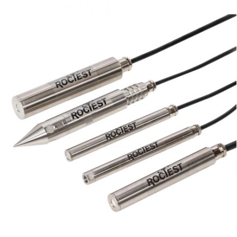
Five models of PW piezometers are available:
The PWS is designed to be embedded in earth fills, at concrete/earth interfaces or inserted into boreholes and smalldiameter pipes. The end of the PWS is fitted with a high or low air entry filter, which protects the sensing element from solid particles, allowing this model to sense only the fluid pressure to be measured. The filter is easily removable in case of saturation.
The PWF is a thick-walled version of the PWS for use in direct burial applications.
The PWC is provided with a pipe thread adapter, thus enabling the piezometer to be used as a pressure transducer.
The PWP is designed to be driven into unconsolidated fine grain materials such as sand, silt or clay. The external housing is a thick-wall cylinder fitted with a conical shoe at one end and an EW drill rod or standpipe thread adapter at the cable entry end.
The PWL is a low-pressure piezometer (35,70 kPa).
SPECIFICATIONS
|
Range1 |
0.0352, 0.0702, 0.2, 0.35, 0.5, 0.75, 1, 1.5, 2, 3, 5, 7 MPa |
||||
|
Accuracy3 |
± 0.1% |
||||
|
Linearity3 |
< ± 0.5% F.S |
||||
|
Resolution with MB-3TL |
0.025% F.S. (min.) |
||||
|
Thermal drift3 |
± 0.1% F.S. / °C |
||||
|
Thermistance |
3 kΩ (see model TH-T) |
||||
|
Cable4 |
IRC-41A, IRC-390, IRC-41AV |
||||
|
MODEL |
PWS |
PWF |
PWC |
PWP |
PWL |
|
Housing |
Slim |
Thick-walled |
Threaded (STD ¼ in -18 NPT male) |
Push-in-point |
‒ |
|
Outside diameter |
19 mm |
28.6 mm |
19 mm |
33.4 mm |
38 mm |
|
Length |
200 mm |
200 mm |
213 mm |
260 mm |
200 mm |
|
Material |
Stainless steel |
||||
|
Filter |
Stainless steel, ~ 50 μm, ~ 10 kPa, low air entry Ceramic, ~ 1 μm, ~ 450 kPa, high air entry |
||||
Other ranges available on request.
1 – MPa = 145 psi
2 – Available only with Model PWL
3 – Specifications achieved in laboratory conditions
4 – PWL must be used with vented cable type IRC‐41AV
+


